
The Zyxel IAP500BE access point is equipped with a multifunctional system LED indicator that provides visual information about the device status, including system boot process, connection to the NCC cloud controller, wireless operation, firmware upgrade, and error conditions.
This article provides a detailed explanation of the Zyxel IAP500BE LED indicator behavior in a table format (color, status, and description), as well as an overview of the device ports and control elements. This information helps network administrators and support engineers quickly diagnose device status without accessing the web interface.
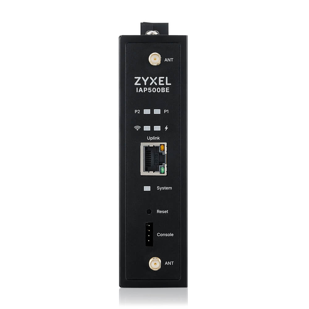 |  |  |
Zyxel IAP500BE Ports, Connectors, and LEDs
This section describes the physical interfaces, connectors, and indicators of the Zyxel IAP500BE access point.
- Ethernet Port (Uplink)
| Port | Description |
|---|---|
| Uplink (RJ-45) | Main Ethernet port used for network connectivity. Supports data transmission and Power over Ethernet (PoE). |
PoE support:
IEEE 802.3at (PoE+)
Used as the primary power source when connected to a PoE-capable switch
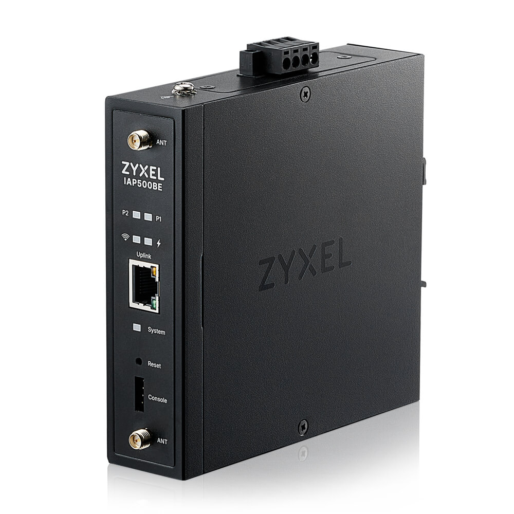
- Power Input (Terminal Block)
| Connector | Description |
|---|---|
| Power Terminal Block | Used for DC power input when PoE is not available |
This connector allows the Zyxel IAP500BE to be powered by an external DC power source via terminal wiring.
- Console Port
| Port | Description |
|---|---|
| Console | Used for local management and troubleshooting via a console connection |
The console port allows administrators to access the device using a console cable for:
Initial setup
Low-level diagnostics
Recovery and troubleshooting when network access is unavailable
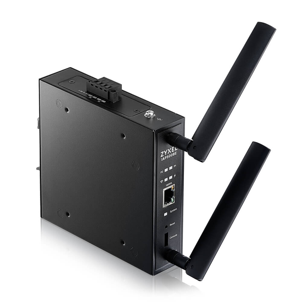
Antenna Connectors
| Connector | Description |
|---|---|
| ANT (Top) | External antenna connector |
| ANT (Bottom) | External antenna connector |
The Zyxel IAP500BE is equipped with two external antenna connectors, allowing the use of external antennas to optimize wireless coverage depending on the deployment scenario.
- Buttons
| Element | Description |
|---|---|
| Reset | Reboots the device when pressed briefly. Press and hold for 5–10 seconds to restore factory default settings |
⚠️ Warning: Factory reset will erase all existing configuration settings.
- Front Panel LED Indicators
The front panel includes the following LED indicators:
System LED — indicates device status
Signal LEDs (P1 / P2) — indicate WiFi signal strength in repeater mode
Uplink LED — indicates Ethernet link and activity
Power LED — indicates power status
(Refer to the System LED and Signal LED tables in the previous sections for detailed LED behavior.)
Zyxel IAP500BE System LED Indicator
System LED indicator descriptions for the Zyxel Device
| COLOR | STATUS | DESCRIPTION | |
|---|---|---|---|
| Amber / Green | Blinks between amber and green alternately (300 milliseconds interval) | The Zyxel IAP500BE is booting up | |
| Amber / Green | Blinks between amber and green alternately (1 second interval) | The Zyxel IAP500BE is discovering the NCC | |
| Amber / Green | Blinks between amber and green alternately 3 times and then turns solid green for 3 seconds | The Zyxel IAP500BE is managed by the NCC but fails to connect and is reconnecting | |
| Green | Slow Blinking (On for 1 second, Off for 1 second) | The wireless module is disabled or has failed, or the device is configured to be managed by the NCC but is not yet registered | |
| Green | Steady On | The Zyxel IAP500BE is ready for use; the wireless interface is active and Wi-Fi clients are connected | |
| Bright Blue | Steady On | The wireless interface is active, but no Wi-Fi clients are connected | |
| White | Slow Blinking (On for 100 ms per second) | Locator LED is enabled. It turns off automatically after the configured time (1–60 minutes, default is 10 minutes). The LED color may slightly vary depending on the model | |
| Blue | Slow Blinking (Blink for 1 time, Off for 1 second) | The Zyxel IAP500BE is performing a Channel Availability Check (CAC) using Dynamic Frequency Selection (DFS) to monitor for radar signals | |
| Red | On | The Zyxel IAP500BE failed to boot up or is experiencing a system failure | |
| Red | Fast Blinking (On for 50 ms, Off for 50 ms) | Firmware upgrade is in progress | |
| Red | Slow Blinking (Blink for 3 times, Off for 3 seconds) | The uplink of the Zyxel IAP500BE is disconnected |
Diagnostic Recommendations
During alternating Amber/Green blinking, wait until the boot process is completed
Do not power off the device while the LED is fast blinking red, as a firmware upgrade is in progress
Use the Locator LED feature to quickly identify the IAP500BE in a rack or deployment site
A solid red LED indicates a critical system error; a reboot and power check are recommended
Signal LED indicator descriptions for the Zyxel Device
| MODE | COLOR | STATUS | DESCRIPTION | |
|---|---|---|---|---|
| Repeater Mode | Green | Steady On | The WiFi signal strength between the Zyxel IAP500BE and the mesh AP is good. The signal strength is greater than -67 dBm. | |
| Repeater Mode | Amber | Steady On | The WiFi signal strength between the Zyxel IAP500BE and the mesh AP is fair. The signal strength is between -80 and -67 dBm. | |
| Repeater Mode | Red | Steady On | The WiFi signal strength between the Zyxel IAP500BE and the mesh AP is weak. The signal strength is below -80 dBm. | |
| AP / Root Mode | — | Off | When the Zyxel IAP500BE is in AP/Root mode, the signal LEDs are off. |
Comments
0 commentsPlease sign in to leave a comment.